System composition
The fatigue loading test system converts the energy of high-pressure liquid into a reciprocating motion of an actuator through an energy conversion and amplification device of an electrohydraulic servo valve, with characteristics of low frequency but large force.
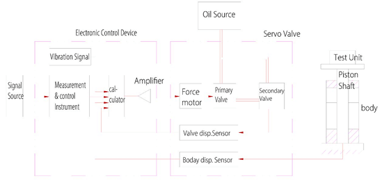
The servo amplifier synthesizes the input signal from the signal source and the feedback sensor signal from servo valve and actuator to generate a deviation signal and amplifies it. When this signal is input to the torque motor of the servo valve, the magnified force acts on the primary slide valve and causes the slide valve to generate a displacement proportional to the force.
A liquid flow proportional to the output displacement of the primary slide valve acts on both ends of the secondary slide valve, so that the speed of the secondary slide valve is proportional to the input current of the torque motor. A displacement sensor at the lower end of the piston rod of secondary slide valve provides a displacement feedback signal to the servo amplifier to form a closed-loop control. The hydraulic source provides a power source with a certain pressure and flow to the servo valve.
The servo valve changes the flowing direction of the high-pressure liquid according to the input signal, so that the cylinder piston and the fixtures and samples loaded on the table will reciprocate (ie, vibration) under the pressure difference between the upper and lower ends.

System schematic
The system is mainly composed of actuators, electro-hydraulic servo valves, electrical control cabinet, articulated and guided components, hydraulic oil source, and pipeline controller.
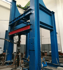
1.1 System loading bracket
The floor-type loading bracket is mainly composed of a work bench with a T-slot, a set of adjustable foundations at the bottom, a beam, and two lateral reaction frames.

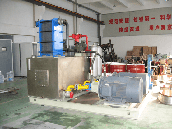
1.2 Hydraulic oil source
Hydraulic power source has functions of start, low pressure, high pressure, and stop. The system starts smoothly and supplies pressure safely. The integrated pressure sensor, liquid level sensor, and temperature sensor are connected to the controller, which can monitor the working status of the hydraulic system in real time; perform safe and reliable self-locking for abnormal conditions; Designed for variable displacement pumps, energy efficient.

E.g. power oil source
2.1 Reliability prediction method
2.1.1 Reliability and Failure Rate
In the engineering design of the fatigue loading test system, the basic units include components, devices, parts, and components, mainly in the following categories:
a) Electronic components, such as resistors, capacitors, diodes, transistors, integrated circuit chips, connectors, etc.;
b) electronic components, such as power modules, crystal oscillators, etc.;
c) mechanical parts, such as hinges, bearings, housings, etc.;
d) Electromechanical supporting components, such as servo valves, motors, various sensors, etc.
2.1.2 Prediction of Failure Rate Design
The failure rate design of the fatigue loading test system is expected to adopt the basic unit classification and counting method, so the failure rate of the basic unit is the basic parameter for system reliability prediction.
The design of the failure rate of the basic unit can be expected to take the following three methods according to the actual situation: look up the table in the relevant design manual, calculate according to technical parameters, and estimate based on experience.
2.1.3 Allocation of reliability indicators
The main principles of reliability index allocation are as follows:
a) For the key parts of the system, the assigned reliability index should be higher;
b) For more complicated sub-systems (units), the assigned reliability index may be lower;
c) For units that are easy to maintain, the assigned reliability index may be lower;
d) For those sub-systems with mature circuit designs, the reliability index can be allocated higher;
e) The distribution results should make the reliability of the system meet the specified indicators.


